Measure Tool
The Measurement Tool allows users to visualize and calculate the lengths and angles of a measurement line projected onto a 3D plane in real-time. This feature is primarily intended to aid in simulations where precise spatial measurements are necessary, such as in offshore operations. The tool includes options to toggle between different projections and customize the alignment of the projection plane.
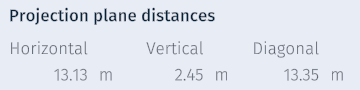
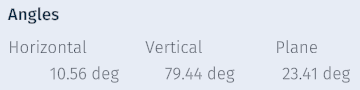
The tool will continuously calculate and update the following: - Vertical Angle: Angle between the moving objects relative to the vertical plane. - Horizontal Angle: Angle between the moving objects relative to the horizontal plane. - Plane Angle: Angle between projections (diagonal to horizontal) as objects move. - Vertical, Horizontal, and Diagonal Lengths: Continuously updated distances between the objects as they change position.
Measure Tool Demonstration
Accessing the Measure Tool


Making a Measurement
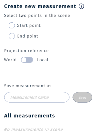
To make a new measurement, press the
 button. A Create new measurment panel appears.
- Left-click to set a start point of the measurement, then left-click once more to set the end point. A red line will indicate the measurement.
- Adjust the points by selecting them individually and moving them using the gizmos.
button. A Create new measurment panel appears.
- Left-click to set a start point of the measurement, then left-click once more to set the end point. A red line will indicate the measurement.
- Adjust the points by selecting them individually and moving them using the gizmos.
Projection Reference
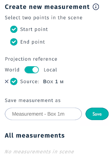
When creating a new measurement, there are two options: World (default) and Local.
A
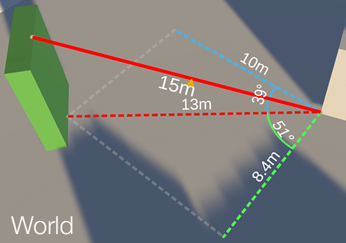
Worldmeasurement measures distances and angles independently from where the measurement starts and ends and is always relative to the world’s axis (North, East, Down).A
Localmeasurement uses an object as a reference point. The object set as a reference source is used for calculating the projecting lines (blue and green), calculated from the object’s X, Y, Z planes.
Projection plane set to World. World’s north, east and down axis are used as references. |
Projection plane set to Local. Green box is set as projection reference source. |
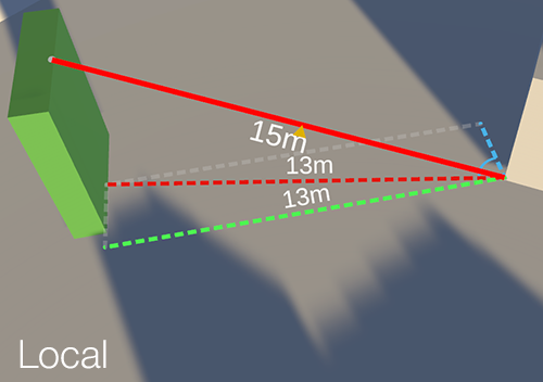
By default, the end point is set as the reference source. You can delete the default reference source and set a new one by left-clicking on the desired object.
Note
A building cannot be set as reference object.
A local projection reference can only be made prior to saving a measurement.
A local measurement can be toggled to be viewed as both a local and world projection reference.
Save Measurement
Once a measurement’s Start point and End point are set, click the
 button to save the measurement. You can give the measurement a different name than what is suggested.
Viewing a Measurement
Select a measurement from the list under the measurement tool in the left-hand menu to see the available options in the Properties Panel
Main measurement
The accurate measurement between the start and end point.

Projection plane
Can be set to Top (xy), Side (xz), and Front (yz).

Reference frame
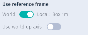
Use toggle button to toggled between local and world frame of reference. If the reference source object is rotated, use the Use world up axis toggle. For more information, see the Projection Reference above.
Projection plane and angle distances
Detailed measurements of the projection planes and angles.
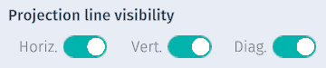
Visibility
Use toggles to hide or show lines and measurements.


Deleting a Measurement
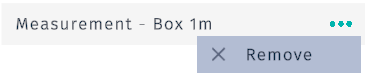
To delete a measurement, left-click the context menu ... and press the Remove button.